

PLEASE SELECT THE DESTINATION COUNTRY AND LANGUAGE :
Product Details
IDR 8

| Price | |
|---|---|
| Discounted Price | Php 195,400.00 |
| Discounted Amount | Total Discounted Amount KRW (Mobile Purchase Discount KRW ) |
| Reward Points |
Points :1,954.00(1.00%)
|
| Shipping Method | Selected by customer |
| Shipping Cost | International Shipping Fee |
| Description |
| Shipping | |
|---|---|
| Quantity |
|
| Product Info | Product | Remove |
|---|---|---|
| Total(Qty) 0 | ||
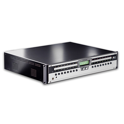
OVERVIEW:
The Allen & Heath iDR System is a set of components whose hardware, control and signal processing flexibility make it well suited to many installed, live sound and special project applications. The 2U rack or desk mount iDR-8 is the main unit in the iDR system having all the DSP (digital signal processing) power needed for 16 input and 16 output channels.
- It has 8 XLR analogue mic/line inputs and 8 XLR analogue line outputs.
- You can add a further 8 inputs and/or 8 outputs bringing it up to a maximum 16x16 matrix by plugging in the iDR-in and/or iDR-out audio expanders.
- The signal can be routed at three key points: the input source patch bay, central matrix, and output source patch bay.
- Although the iDR does not work with networked audio, the expanders can be located up to 250 metres away so providing remote analogue audio inputs and outputs connected using CAT5 cables.
- You can also daisy chain multiple iDR-8 units in a distributed system.
- The units are linked using an 8 channel wide bus which plugs into the digital expander ports. Maximum matrix at any unit is 16x16 which includes the interconnecting bus.
- Several iDR-8 units can be linked in this way, but you can have only one iDR-in and one iDR-out expander per system.
A stereo audio monitor is included. This has both input and output TRS jacks so that the monitor can ‘ripple through’ chained iDR units. It also feeds a front panel headphones socket for local monitoring of any point in the audio signal path. The monitor can access the input and output channels so that they can be used with the matrix. For example, you can achieve a 10x10 matrix from an unexpanded iDR-8. A built-in signal/noise generator provides a further source which can be routed to the input channels for test and line up purposes.
There are many operator control possibilities. You can configure the 16 front panel keys and 32 3-colour LEDs, and use the DR-Link port to add up to 3 iDR-switch units for up to 72 additional switch closure and 48 open-collector logic outputs. In addition you can choose two of the following: MIDI, the Sys-Net serial port to interface with third party remote controllers, RS232 for modem communication, and the PL-Anet serial port for running a network of Allen & Heath PL wall plates and controllers.
- The iDR-8 features networked control. It is configured using the iDR System Manager software via an Ethernet port either connected directly to the installer’s PC, or over a TCP/IP network.
- The PC control can be password protected for security.
- Once configured it runs stand alone using its built-in iDR Unit software with stored settings.
- iDR units can also be operated from networked PC workstations running PL Client software configured as ‘virtual’ wall plates by the installer using PL Designer software.
- An RS232 modem port lets the installer remotely interrogate units. A front panel RS232 port allows easy operating code update.
The iDR system offers tremendous flexibility. The system set up is stored in patches. Up to 99 patches can be programmed. You can decide which parameters are affected by each. To make best use of this it is important that you plan your installation carefully before you start. You can try out, prepare and archive different configurations offline before plugging in. Virtual panels and controllers are displayed so you can simulate how it will work for real. You can program the unit name, clock and IP address, and check diagnostic information and audio signal presence using the front panel menus accessed by removing the face plate. You can also attach your custom label here so that it is protected when the plate is refitted. For further information on the configuration of the unit please refer to the Help files which come with the software.
Main Features:
- iDR-8 main processing unit 2U, 8 mic/line in, 8line out audio mix processor with 16x16 channel matrix. The heart of the iDR system, it features 2 24bit Motorola DSPs.
- Daisy chain iDR-8 units. Any number may be interconnected via the 8 channel digital bus using CAT5 cable. Many possibilities for flexible sound system solutions.
- iDR-in- 1U, 8 mic/line input expander unit. Expands the number of inputs to 16. Can be up to 250 metres away for remote audio. Uses CAT5 digital link. One input expander per iDR system.
- iDR-out - 1U, 8 line output expander unit.Expands the number of outputs to 16. Can be up to 250 metres away for remote audio. Uses CAT5 digital link. One output expander per iDR system.
- iDR-switch -1U add-on unit providing 24 contact closure switch inputs and 16 open collector logic outputs. Up to 3 units may be daisy chained for a maximum 72 switch and 48 logic outputs. Each unit can be separated by up to 250 metres. Connects via the DR-Link serial port.
- PL wall plates and remotes - The Allen & Heath range of optional wall plates and controllers for remote switch, rotary encoder, infra-red, fader, LED indicator and logic output control. Connects via the PL-Anet serial port.
- Desk top or 19” rack mounting - Rubber feet and removable rack ears provided.
- Universal mains power input - automatically detects worldwide voltage from 100V to 240V AC.
- Removable face plate - for accessing front panel setup menu system, RS232 connector and status indicators. Also provides a protected custom label facility.
- XLR mic/line inputs - Electronically balanced, pin 2 hot, for microphone or line level equipment. Soft control of gain, pad switch and 48V phantom power. No internal adjustments needed.
- XLR line outputs - Electronically balanced, pin 2 hot, 0dBu with +18dB headroom.
- Stereo audio monitor - with front panel headphones socket and rear panel TRS jacks. Can monitor any point in the audio chain using manual or mouse selection. Can be used with the audio matrix as two additional channels, for example providing a 10x10 matrix from an unexpanded iDR-8.
- Network port - connects to a PC or network for control using the iDR System Manager, PL Client software, Telnet, TCP/IP, remote access etc.
- RS232 ports on front and rear - for connection to a PC for code update and to a modem for remote system interrogation.
- SysNet port - for control by third part touch screens and other remote controllers.
- MIDI port IN, OUT and THRU sockets - provided for remote control using show controllers and other MIDI equipment.
- 16 Front panel soft keys - can be assigned by the installer as level, mute or patch recall with different types of press action. Similar applies to the iDRswitch functions.
- 32 Front panel 3-colour soft LEDs - can be assigned by the installer as signal meters, mute or patch related indicators.
- Front panel LCD display A 16 character 2 line LCD can display combinations of clock, patch name, unit name and user defined text. This can be linked to the patches.
- iDR System Manager software - for system setup. Once configured the PC can be removed and the system operated stand alone.
- PL Designer and Client software - for creation of ‘virtual’ wall plates and controllers that can be run from networked PC workstations. Operator control can be restricted by the installer.
- Powerful fixed architecture - with full processing on all 16 input and output channels. Familiar GUI makes setup and control an easy task.
- 48kHz operation - The iDR-8 has processing for a full 16x16 matrix running at 48kHz. An upgrade to 96kHz may become available in the future.
- Patchbays and crosspoint matrix - The input source patchbay selects any physical input to any input channel. The output patchbay selects any output channel to any physical output. The 16x16 matrix allows independent level control at each crosspoint.
- Channel stereo linking and grouping - Input and output channels can be linked for true stereo operation, and grouped for master fader control.
- Configurations can be named, archived and pened using PC files. These store the system setup parameters such as communication options, names, stereo linking, scheduled events and set of patches.
- Patches - Up to 99 patches can be created, named and stored within the configuration file. A patch can work with any number of selected parameters including signal processing, soft key and LED settings. This provides a unique flexibility in setting up complex changes with simple operator control.
- Time and day of week - for display on the unit LCD, and for scheduled event patch recalls using the internal iDR-4 clock.
- Naming - Input channels, output channels, fader groups and PL devices can be named.
- Channel processing - Includes faders, mute, polarity reverse, delay, parametric EQ, crossover filters noise gates, compressors and limiters.
- Ducking, AMM and paging - System functions include a 16 priority level ducker, automatic mic mixer and two independent pagers.
- Signal generator - provides sine wave, white, pink and band pass noise signals for system line up and test
- DR DSP system
- 16 processing channels (inputs and outputs)
- 8 analogue mic/line inputs on XLR with 48V phantom power
- 8 analogue line outputs on XLR
- iDR-8ST version also available, with XLRs replaced by Euroblock (Phoenix) connectors
- 2 line inputs on TRS jack
- 2 line outputs on TRS jack
- Digital audio expansion ports (8 channels in, 8 channels out)
- Hot Plug‘n’Play PL Series remote controllers
- High Quality Audio Signal Path and DSP processing
- Headphone monitor with mouse and ripple-through capability
- MIDI In/Out/Thru connections
Front Panel Features:
Shown with face plate removed.
1)Rack ears Mount the unit into a standard 19” equipment rack. Can be removed for stand alone desk or shelf mounting.
2) Rubber feet Provided separately. Press these into the base holes for stand alone desk or shelf mounting.
3)Write-on label strip To mark up the soft key and LED functions using a suitable marker pen or adhesive label. A Windows™ Word template is provided with the software.
4) Face plate fixing holes Fit the face plate using the four M3 screws provided once the unit is configured and labels fitted. A suitable 2mm hex Allen key is supplied.
5) LCD display Displays system information on a backlit 2x16 character LCD display. You can configure this to display different combinations of clock, patch name, unit name and user defined text.
6)Soft LEDs 32 3-colour LED indicators referred to as ‘soft’ because they can be assigned by the installer as audio meters, mute or patch related indicators. They can display red, green or yellow.
7) Soft keys 16 momentary action switches which can be assigned by the installer as level, mute or patch recall.
8) Headphones output A front panel socket is provided for stereo headphone monitoring. The level trim can be adjusted using a flat bladed screwdriver
9) Front panel RS232 port This is used for code update from a PC via its RS232 COM port. It can also be used for system configuration or checking using iDR System Manager software but the faster network port is recommended.Pressing the FRONT/REAR switch selects either the front or rear RS232 port. The active LED lights when the port is available.
10) Code update switch Puts the unit into code update mode ready to accept new operating code from a PC. Status is shown on the LCD.
11)Status LEDs Both the slave and ext sync lock LEDs light when the unit is correctly working as a slave in a daisy chained iDR system. The 96k LED is available for a possible future upgrade.
12) Menu key Press and hold this key for 2 seconds to access the setup menus. These let you set up the clock, unit name, TCP/IP and PPP communication parameters, select points in the channel signal path to monitor, and check system diagnostics.
13)Scroll keys 4 keys are used to access the setup menus and change parameter values. The and keys are also used when the soft keys are assigned as up/down level controls.
Rear Panel Features:
1.) Mains input - Use the IEC lead with moulded mains plug suitable for your local mains voltage. The protection fuse rating is marked on the rear panel. The on/off switch is positioned on the rear panel to prevent accidental operation.
2.) Network port - RJ45 socket for connection to an Ethernet network or PC using UTP CAT5 cable.This port is recommended for configuring the system with iDR software. The MDI/X switch selects network or direct to PC operation. The link LED lights when communication is established. The TX LED lights when data is communicated.
Note: The RS232, MIDI, SysNet and PL-Anet control ports are not all available at the same time.A combination of two is selected using iDR System Manager. The associated active LED lights when the port is available.
3.) RS232 (MODEM) port - This is used for connection to a modem so that the unit can be interrogated by a remote PC over a standard telephone line. It can also be used for system configuration using iDR System Manager software but the faster network port is recommended.Pressing the front panel switch selects either the front or rear RS232 port.
4.) MIDI port - Standard opto-isolated MIDI port with IN, THRU and OUT connectors.
5.) SysNet port - An RS232 serial port for communication with third party remote controllers running the Allen & Heath SysNet protocol.
6.) PL-Anet port -An RS485 serial port for communication with a network of Allen & Heath PL wall plates and remote controllers using CAT5 STP cable
7.) DR-Link port - RJ45 socket for control of iDR audio and logic expander units using CAT5 STP cable. IN and OUT ports are provided on the expander units so that the control can be daisy chained through a system with more than one expander.
8.) Audio expander ports - RJ45 sockets for communicating 8 channel digital audio between the iDR-8 and its expanders using CAT5 STP cable. Two cables are required between the expander and iDR-8, one for the audio, the other for DR-Link control.
9.) Mic/Line inputs - Balanced XLR inputs for microphone and line level sources. Adding the iDR-in expands the iDR-8 to 16 inputs.
10.) Audio outputs - Balanced XLR line level outputs with maximum +18dBu level. Adding the iDR-out expands the iDR-8 to 16 outputs.
11.) Monitor inputs and outputs - Balanced TRS jacks for L and R monitor inputs and outputs. These provide a line level version of the front panel stereo headphones output and can daisy chain through multiple iDR units
Dimensions:
Specifications:
| Product Name | IDR 8 |
|---|---|
| Brand | ALLEN&HEATH |
| Sale Price | Php 195,400.00 |
| Mileage | Points :1,954.00 |
| 수량 |   |
| Product Code | P0000GBE |
| Product Details | 16X16 Matrix Mixer |
| QR Code |    |
Payment
Shipping
- Shipping Method : Selected by customer
- Shipping Area : Nationwide, Worldwide
- Shipping Cost : International Shipping Fee
- Shipping Time : 2 - 6 days
- About Shipping :
Returns/Exchanges
Refunds
The Eight Basic Consumer Rights : http://www.dti.gov.ph/dti/index.php?p=720