

PLEASE SELECT THE DESTINATION COUNTRY AND LANGUAGE :
Product Details
OP 78

| Price | For Inquiry |
|---|---|
| Discounted Price | |
| Discounted Amount | Total Discounted Amount KRW (Mobile Purchase Discount KRW ) |
| Reward Points |
Points :751.00(1.00%)
|
| Shipping Method | Selected by customer |
| Shipping Cost | International Shipping Fee |
| Description |
| Shipping | |
|---|---|
| Quantity |
|
| Product Info | Product | Remove |
|---|---|---|
| Total(Qty) 0 | ||
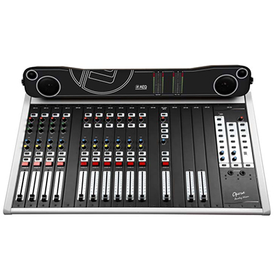
Overview:
The monitoring and power supply module, OP-78, carries out the functions of:
- Studio and control room monitoring.
- Talkback management.
- System general power supply.
- Master and PFL Vu-meters control, located up-front on the chassis.
- Feeds the PFL speakers located beside the Vu-meters.
Due to this, this module can be divided in the following sub-blocks:
- Control room monitor and metering module “CONTROL MONITOR”.
- Studio room monitor module “STUDIO”.
- Talkback, PFL and intercom module “TALKBACK”.
- Power supply.
Module Features:
- Control room monitor and metering block ” CONTROL MONITOR”.
This block manages the signal sends to the control room monitors.
- The master output signal is sent pressing the MASTER selector (4), the auxiliary output signal is sent by means of the AUX selector (3), the PFL by means of the PFL selector (6), and the external signals that are coming in through the I/O CONNECTOR (36) are sent by means of their respective EXT1 (7) and EXT2 (8) selectors.
- The level of the signal or signals selected for control room monitoring is adjusted by means of the MONITOR LEVEL rotary control (9), for the control room speakers, and by means of the H/PHONES LEVEL rotary control (10) if the H/PHONES headphones outputs (12 and 13) (located on the lower part of the module) are used. This level can be metered on the PFL/SEL VU-Meter if the switch (3) PFL/SEL is pressed selecting SEL.
- In this block two function modes can be selected, studio control or self-operation, by means of the NORMAL/AUTOCONTROL selector (11).
- The NORMAL mode allows the muting of the studio room speakers and the connection of signalling on opening any microphone module.
- If AUTOCONTROL (self-operation) mode is selected by means of the selector (11), the control room speakers are also muted when any microphone channel is opened.
- This block also delivers the signal to the PFL speakers and the metering instruments. The mixer is fitted with two VU-meters. One of them is assigned permanently to master (L and R), and the other one to PFL/SEL.
Nonetheless, the function of both VU-meters can be modified by means of the configuration jumpers located on the rear part of the VU-meter board:
- PDP3 (1-C), PDP1 (1-C): Master assignment.
- PDP3 (3-C), PDP1 (3-C): PFL/SEL assignment.
- PDP4 (2-C), PDP2 (2-C): Auxiliary assignment.
The 0 Vu adjustment is carried out by means of the potentiometers P1 and P2 on the same board. To access this board, remove the mixer’s rear panel.
Studio room monitor block “STUDIO“.
- The ‘STUDIO’ block manages the signal sends to the studio room monitors.
- The master output signal is sent pressing the MASTER selector (14), the auxiliary output signal is sent by means of the AUX selector (15), the PFL by means of the PFL selector (16), and the external signals that are coming in through the I/O CONNECTOR (36) are sent by means of their respective EXT1 (17) and EXT2 (18) selectors.
- The level of the signal or signals selected for monitoring in the control room is adjusted by means of the MONITOR LEVEL rotary control (19), for the studio room speakers, and by means of the H/PHONES LEVEL rotary control (20) for the studio room headphone outputs, located on the I/O CONNECTOR (36). There are two outputs for headphone connection, named PRIMARY
- HEADPHONES and SECONDARY HEADPHONES. The signal is the same on both outputs.
- This block also cancels all PFL assignments on the various channels, when the PFL RESET button (21) is pressed.
Talkback, PFL and intercom block “TALKBACK“.
This module manages a series of functions that complete the AEQ OPERA functionality and performance. Below, each one of them is explained in detail.
This block allows talkback by means of the included MIC T'BACK microphone (28) to:
- Master outputs (to OP-60), pressing the MASTER selector (23). If you want to deactivate this function, remove the jumpers from PDP3 and PDP4 and place them on PDP5 and PDP6.
- Auxiliary outputs (to OP-40), pressing the AUX selector (24). If you want to deactivate this function, remove the jumpers from PDP7 and PDP8 and place them on PDP9 and PDP10.
- Telephone outputs (to OP-33), pressing the PHONE selector (25). The jumpers PDP1 and PDP2 allow (when they are placed) the talkback to be sent to the telephone bus 1 and/or 2 respectively.
- Studio room monitors and headphones (on I/O CONNECTOR (36)), pressing the STUDIO selector (26).
- 4-wire intercom mode communication (on I/O CONNECTOR (36)), pressing the INTERCOM selector (27).
- It also allows the PFL speaker level adjustment by means of the SPEAKER LEVEL rotary control (22).
- This rotary control also controls the level of the input signal of the intercom I/O CONNECTOR (36) when this input is activated by means of the INTERCOM switch (29).
- The intercom input and output is only active when the INTERCOM INPUT ON switch (29) is pressed
Power supply.
- The monitoring module includes the mains AC MAINS connector with an EMI filter and a fuse (33), POWER switch (34), as well as two status indicators, + V ANALOG (1) and - V ANALOG (2), located in the front of the module. Their task is to indicate the internal system voltages.
- Inside the mains connector two 1.6A slow type fuses are placed, one of them as spare part.
- In the control room monitor module, when jumper PDP1 is short-circuited, it connects the appliance’s analogue ground with the mains earth.
Signalling:
Below is shown the connection and wiring diagram of the signalling system.
AEQ OPERA STUDIO Analog Broadcast Mixer :
| Product Name | OP 78 |
|---|---|
| Brand | AEQ |
| Sale Price | For Inquiry |
| Mileage | Points :751.00 |
| 수량 |   |
| Product Code | P0000GKB |
| Product Details | Monitoring and Intercommunication Module for OPERA Mixer |
| QR Code |    |
Payment
Shipping
- Shipping Method : Selected by customer
- Shipping Area : Nationwide, Worldwide
- Shipping Cost : International Shipping Fee
- Shipping Time : 2 - 6 days
- About Shipping :
Returns/Exchanges
Refunds
The Eight Basic Consumer Rights : http://www.dti.gov.ph/dti/index.php?p=720
Product Inquiry
Seller Info
Related Items
-

For Inquiry
-
For Inquiry
-

For Inquiry